")


Cooling
The motors are cooled by their own ventilation (IC 411 acc. With IEC 60034-6) and are equipped with a synthetic two-way axial fan. The motors must be mounted in such a way as to ensure a minimum distance between the fan cover and the nearest component so that air circulation is not affected. Motors from IEC frame size 63 and above can be equipped with an independently operating external fan if required. Cooling then takes place via an axial fan mounted on a standard fan cover. This design should be installed in cases where the motor works with a frequency converter. Then the motor can operate at constant speed, at lower rotational speeds or at a higher input frequency. Motors with a second shaft are excluded from this option.
Insulation class
Motors are equipped with class F insulation materials (enamel wire, insulation materials, impregnation resin) as standard. Standard motor design generally stays below the maximum temperature limit of 80K, which conforms to Class B excess temperature. Careful choice of system component insulation allows motors to be used with frequency converter operations in tropical conditions and at normal vibration levels. If you plan to use the engine in a chemically aggressive environment or in places with high humidity, we recommend contacting the customer center. On request, the engines can also be supplied with the H specification class.
Type of protection
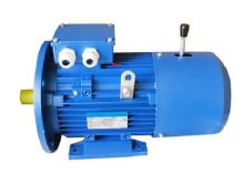
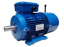
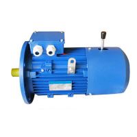
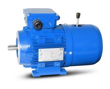
As standard, the motors are supplied with IP55 protection. If necessary, it is possible to supply a higher level of protection. All motors installed outdoors must be protected from direct sunlight. If they are mounted vertically with the shaft pointing down, in which case the motor should include a cover to protect against water and other foreign particles.
Winding Thermal Protection
Motors can be equipped with integrated thermal probes to protect the windings from excessive temperature in cases of insufficient ventilation or overload. Motors that use frequency converter operation should still have additional protection. The following protection options are available:
Z-TO: Three bimetallic probes with a response temperature of 150 °C in the winding.
This protective device contains an encapsulated bimetallic strip that opens circuit contacts in the event of overheating. If the temperature drops again, the contacts close. These three bimetallic strips with normally closed contacts are usually connected in series on an auxiliary terminal block.
Z-DK: Three PTC thermistors with a response temperature of 150 °C.
They are used as standard for frame sizes 160-355. These thermistors contain a semiconductor that shows magnitude changes in resistance only before overheating. Thermistors with a positive temperature coefficient are commonly used. The advantage of these sensors is that they can detect small temperature differences in a very reliable time and show no signs of use. Unlike bimetallic temperature probes, thermistors cannot directly switch the relay circuit, so a special trip unit must be installed. Three PTC thermistors are connected in series on the auxiliary terminal block.